Ero sivun ”Apple II” versioiden välillä
Tnt (keskustelu | muokkaukset) (Ak: Uusi sivu: W. Gayler - The Apple II Circuit Description p. 87 == Cassette Tape == The Apple II can store and retrieve digital data using a standard audio cassette tape recorder. The hardwa...) |
Tnt (keskustelu | muokkaukset) |
||
| Rivi 16: | Rivi 16: | ||
Data to be recorded on tape is formatted into records. Each record consists of several seconds of header tone followed by a sync bit, the actual data, and a check sum. Binary files and machine code are recorded as one record (Fig. 7-6A). BASIC programs are recorded as two records (Fig. 7-6B). The first record contains the BASIC program's length in the record's data field. The second record contains the BASIC program itself. | Data to be recorded on tape is formatted into records. Each record consists of several seconds of header tone followed by a sync bit, the actual data, and a check sum. Binary files and machine code are recorded as one record (Fig. 7-6A). BASIC programs are recorded as two records (Fig. 7-6B). The first record contains the BASIC program's length in the record's data field. The second record contains the BASIC program itself. | ||
| + | |||
| + | [[Tiedosto:ISBN_0-672-21959-X_Fig_7-6.png]] | ||
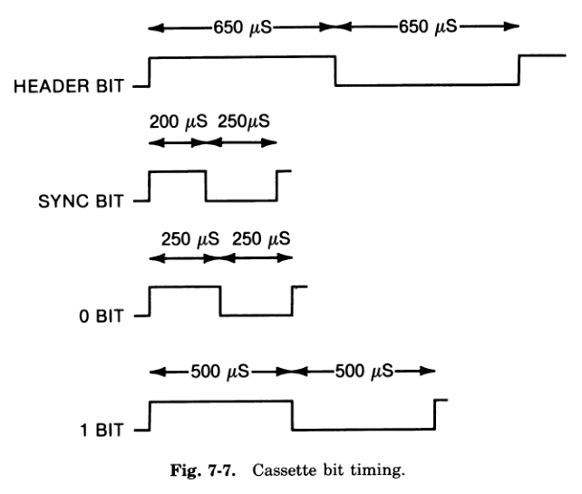
Fig. 7-7 shows individual bits or cycles of the tones that make up the format. The times shown are approximate, but they are within 2% of measured values. The header tone consists of half cycles of 650 microseconds each. This is a frequency of 770 Hz. The sync bit contains one-half cycle of 200 microseconds followed by one-half cycle of 250 microseconds. A 0 bit consists of two 250 microsecond half cycles. Data of all 0's would be a tone of 2000 Hz. A 1 bit consists of two half cycles of 500 microseconds each. Data of all 1's would be a 1000-Hz (l-kHz) tone. It takes 500 microseconds to transmit a 0 and 1000 microseconds to transmit a 1. The average transmission rate for random data is therefore 1333 bits per second. | Fig. 7-7 shows individual bits or cycles of the tones that make up the format. The times shown are approximate, but they are within 2% of measured values. The header tone consists of half cycles of 650 microseconds each. This is a frequency of 770 Hz. The sync bit contains one-half cycle of 200 microseconds followed by one-half cycle of 250 microseconds. A 0 bit consists of two 250 microsecond half cycles. Data of all 0's would be a tone of 2000 Hz. A 1 bit consists of two half cycles of 500 microseconds each. Data of all 1's would be a 1000-Hz (l-kHz) tone. It takes 500 microseconds to transmit a 0 and 1000 microseconds to transmit a 1. The average transmission rate for random data is therefore 1333 bits per second. | ||
Data is recorded low byte first. Within each byte the MSB is recorded first. | Data is recorded low byte first. Within each byte the MSB is recorded first. | ||
| + | |||
| + | [[Tiedosto:ISBN_0-672-21959-X_Fig_7-7.png]] | ||
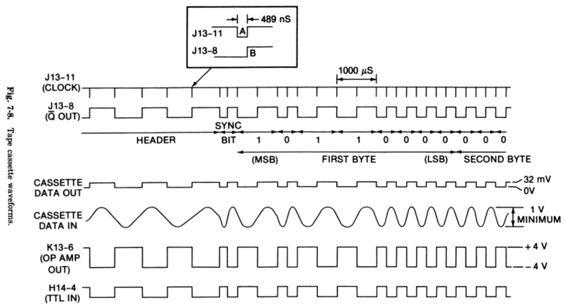
Fig. 7-8 shows typical tape cassette waveforms near the time of the sync bit. When the cassette output ($C020-$C02F) is accessed, J13-11 goes low for 489 nS (point A). On J13-11's rising edge, J13-8 is clocked (point B). Since J13-8 connects to JL3-I2 (Fig. C-12*), this flip-flop will toggle when clocked. In Fig. 7-8 we have shown the last two and one-half cycles of the header tone. The sync bit comes next, followed by the first data byte. In this example, the first byte is $B0 or 10110000 (binary). | Fig. 7-8 shows typical tape cassette waveforms near the time of the sync bit. When the cassette output ($C020-$C02F) is accessed, J13-11 goes low for 489 nS (point A). On J13-11's rising edge, J13-8 is clocked (point B). Since J13-8 connects to JL3-I2 (Fig. C-12*), this flip-flop will toggle when clocked. In Fig. 7-8 we have shown the last two and one-half cycles of the header tone. The sync bit comes next, followed by the first data byte. In this example, the first byte is $B0 or 10110000 (binary). | ||
| Rivi 34: | Rivi 38: | ||
At this point we must discuss how the cassette signal gets through data selector H14 (Fig. C-12*).If the address is in the range $C060-$C06F, then F13-9 will go low during ϕ2. This enables H14 via pin 7. Data selector H14 selects one of its eight inputs as a function of address lines AD0, AD1, and AD2. When the address is $C060 or $C068 (AD0, ADl, and AD2 all equal 0), H14 is enabled and selects input pin 4 to output on pin 5. Pin H14-5 connects to data bus bit 7. Thus, at either of these addresses, the cassette input is put on data bus bit 7. Bit 7 is used since it is easily tested by various 6502 instructions. Since ADB is not decoded by this part of the circuit, there are two addresses eight locations apart that can access the cassette input. In such cases, we usually use the lower address ($C060). | At this point we must discuss how the cassette signal gets through data selector H14 (Fig. C-12*).If the address is in the range $C060-$C06F, then F13-9 will go low during ϕ2. This enables H14 via pin 7. Data selector H14 selects one of its eight inputs as a function of address lines AD0, AD1, and AD2. When the address is $C060 or $C068 (AD0, ADl, and AD2 all equal 0), H14 is enabled and selects input pin 4 to output on pin 5. Pin H14-5 connects to data bus bit 7. Thus, at either of these addresses, the cassette input is put on data bus bit 7. Bit 7 is used since it is easily tested by various 6502 instructions. Since ADB is not decoded by this part of the circuit, there are two addresses eight locations apart that can access the cassette input. In such cases, we usually use the lower address ($C060). | ||
| + | |||
| + | [[Tiedosto:ISBN_0-672-21959-X_Fig_7-8.png|800px|thumb|left]] | ||
| + | <br clear=all> | ||
Routines in the monitor scan bit 7 at location $C060 every 12.8 microseconds looking for a transition. By measuring the time between transitions, the routines can distinguish between header, sync, 0, and 1 bits. | Routines in the monitor scan bit 7 at location $C060 every 12.8 microseconds looking for a transition. By measuring the time between transitions, the routines can distinguish between header, sync, 0, and 1 bits. | ||
| Rivi 40: | Rivi 47: | ||
| − | + | [[Tiedosto:ISBN_0-672-21959-X_Fig_C-12.png|800px|thumb|left]] | |
Nykyinen versio 3. joulukuuta 2017 kello 00.56
W. Gayler - The Apple II Circuit Description
p. 87
Cassette Tape
The Apple II can store and retrieve digital data using a standard audio cassette tape recorder. The hardware involved is fairly simple; all the intelligence is in the firmware. When you store a program, routines in the monitor ROM cause flip-flop J13-9 (Fig. C-12*) to generate square or rectangular waveforms. Thus, J13-8 then drives the CASSETTE DATA OUT jack. This jack is meant to be connected to the microphone input of the recorder.
The earphone output of the recorder connects to the CASSETTE DATA IN jack of the Apple. When you load a program, the signals from the tape pass through operational amplifier K13, then appear at an input of data selector H14. The 6502 can read the output of H14 under program control. The program (again in the monitor ROM) then processes the cassette signal to reproduce the data.
pp. 93-96
Detailed Circuit Analysis - Cassette Tape
In this section we will describe the hardware involved in writing and reading cassette tapes. We will also touch on some aspects of the cassette system that are actually determined by the firmware.
Data to be recorded on tape is formatted into records. Each record consists of several seconds of header tone followed by a sync bit, the actual data, and a check sum. Binary files and machine code are recorded as one record (Fig. 7-6A). BASIC programs are recorded as two records (Fig. 7-6B). The first record contains the BASIC program's length in the record's data field. The second record contains the BASIC program itself.
Fig. 7-7 shows individual bits or cycles of the tones that make up the format. The times shown are approximate, but they are within 2% of measured values. The header tone consists of half cycles of 650 microseconds each. This is a frequency of 770 Hz. The sync bit contains one-half cycle of 200 microseconds followed by one-half cycle of 250 microseconds. A 0 bit consists of two 250 microsecond half cycles. Data of all 0's would be a tone of 2000 Hz. A 1 bit consists of two half cycles of 500 microseconds each. Data of all 1's would be a 1000-Hz (l-kHz) tone. It takes 500 microseconds to transmit a 0 and 1000 microseconds to transmit a 1. The average transmission rate for random data is therefore 1333 bits per second.
Data is recorded low byte first. Within each byte the MSB is recorded first.
Fig. 7-8 shows typical tape cassette waveforms near the time of the sync bit. When the cassette output ($C020-$C02F) is accessed, J13-11 goes low for 489 nS (point A). On J13-11's rising edge, J13-8 is clocked (point B). Since J13-8 connects to JL3-I2 (Fig. C-12*), this flip-flop will toggle when clocked. In Fig. 7-8 we have shown the last two and one-half cycles of the header tone. The sync bit comes next, followed by the first data byte. In this example, the first byte is $B0 or 10110000 (binary).
Note that on power-up, J13-8 can be either low or high. The processor can neither initialize nor read the state of J13-8. As a result, the J13-8 waveform could be inverted from what is shown in Fig. 7-8. No matter in which state J13-8 starts, it toggles every time J13-11 goes high. That is all that matters.
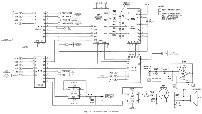
Resistors R18 and R19 attenuate J13-8 to about 0.8%, or 32 mV peak-peak open circuit. The attenuated signal appears at the CASSETTE DATA OUT jack of the Apple. It is connected to the microphone input of the recorder when data is stored. This concludes the discussion of the hardware used in the write direction. We now turn our attention to the read process.
On data retrieval, the earphone jack of the recorder connects to the CASSETTE DATA IN jack of the Apple. There may or may not be a polarity inversion in going through the recorder; it does not matter. The cassette input is ac coupled by C10 and attenuated to 50% by R17 and R30. The signal then connects to the inverting input of operational amplifier K13.
Operational amplifier K13 is wired to act as a comparator. Ground through R16 provides an average comparator threshold of 0 volt and R15 provides about 100 mV of hysteresis at the input of the comparator. This circuit arrangement is called a zero crossing detector. The minimum cassette input that produces good results is about 1 volt peak-peak. While reading tapes, the output of K13 swings from plus-saturated to minus-saturated, or about ± 4 volts.
Resistor R29 limits current out of the input of H14 when K13-6 is low. Resistor R29 and the input clamping diode of H14 effectively convert the signal to a TTL level at H14-4. Note that the signal is inverted by K13. Except for an inversion, the TTL signal at J13-8 has been recreated at Hl4-4. To see this, compare the waveforms for J13-8 and H14-4 as shown in Fig. 7-8.
At this point we must discuss how the cassette signal gets through data selector H14 (Fig. C-12*).If the address is in the range $C060-$C06F, then F13-9 will go low during ϕ2. This enables H14 via pin 7. Data selector H14 selects one of its eight inputs as a function of address lines AD0, AD1, and AD2. When the address is $C060 or $C068 (AD0, ADl, and AD2 all equal 0), H14 is enabled and selects input pin 4 to output on pin 5. Pin H14-5 connects to data bus bit 7. Thus, at either of these addresses, the cassette input is put on data bus bit 7. Bit 7 is used since it is easily tested by various 6502 instructions. Since ADB is not decoded by this part of the circuit, there are two addresses eight locations apart that can access the cassette input. In such cases, we usually use the lower address ($C060).
Routines in the monitor scan bit 7 at location $C060 every 12.8 microseconds looking for a transition. By measuring the time between transitions, the routines can distinguish between header, sync, 0, and 1 bits.
p103


